


Process and Instrumentation Diagrams
Process and Instrumentation Diagrams, also known as P&IDs, are basically maps meant to show process connections and equipment relationships pictorially. They are invaluable during the planning and installation of new equipment, maintenance planning and procedures, and when comparing as-installed controls to the original design. This module will discuss how P&IDs are used, how to read the symbols used on P&IDs, and a real world examples of a P&ID system.

Demos + Pricing
Learn more about our courses, get pricing, and see our platform.
Course Details
Learning Objectives
• State the role that P&IDs play in safety
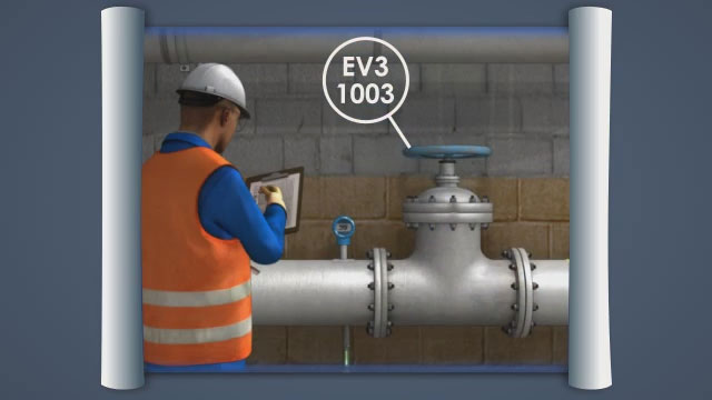
• Differentiate between diagram and physical placement
• Identify the major components of a P&ID sheet
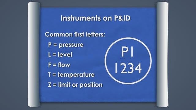
• Describe the different types of symbols found on the P&ID sheet
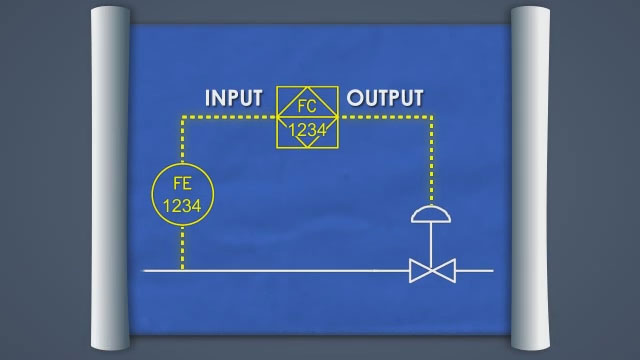
• Follow a process flow by identifying the components, lines, and instrumentation
Specs
Frequently Asked Questions
What is a process and instrumentation diagram (P&ID)?
What are three purposes of a P&ID?
Are P&IDs drawn to scale?
Are the physical placement of equipment within a P&ID accurate?
What type of eqiument is most often found on a P&ID legend?
Sample Video Transcript
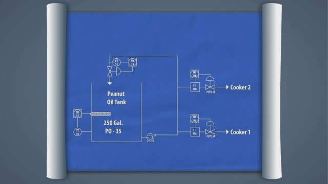
A P&ID shows a process designed in a logical manner. The drawings typically include process flows, and describe the basic control functions. The P&ID shows all process components, and provides a solid reference point for troubleshooting process problems. P&IDs also provide the basis for hazard analysis before actual physical installation of a process. The P&ID is a tool for maintenance and operations to help troubleshoot problems. As the process is changed or updated, the P&ID should be updated to track changes and provide a historical record of the process. The amount of detail in a P&ID set needs to be complete enough for personnel to understand how equipment is operated without so much detail that it is hard to follow.