


Electrical Drawings and Schematics
This course discusses recognizing electronic symbols, integrated circuits, and logic symbols. It also covers electronic schematics and the difference between logic and digital diagrams.


Demos + Pricing
Learn more about our courses, get pricing, and see our platform.
Course Details
Learning Objectives
By the end of this course, you will be able to:
- Identify different types of electrical diagrams
- Describe the purpose of a block diagram
- Describe the purpose of a schematic diagram
- Identify some of the common symbols used in a schematic
- Describe the purpose of a layout diagram
- Describe the purpose of a wiring diagram
- Identify and describe the purpose of cross-references
Specs
Frequently Asked Questions
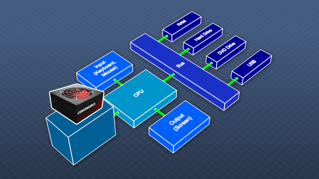
What is a block diagram?
Block diagrams are “high-level”, conceptual diagrams. Block diagrams consist of connected blocks, which represent overall functionality rather than individual components, and show how the functions are related to one another.
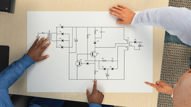
What is an electronic schematic?
An electronic schematic is a diagram that uses standardized electronic and electrical symbols to show how individual components are connected together in a circuit.
How are schematics typically laid out?
How are schematics typically laid out?
Generally, schematics are laid out to read like text in a book. The flow of the power or main signal is from left to right and from top to bottom.
How are connections shown in a schematic?
Connections between components in a schematic are shown with lines. A good schematic will be laid out to minimize the crossing of lines, but crossing is unavoidable.
Why are layout diagrams created?
A layout diagram is created to develop and then implement the most efficient way to arrange and connect a given set of components on a board.
Sample Video Transcript
Block diagrams are “high-level”, conceptual diagrams. Block diagrams consist of connected blocks which represent overall functionality rather than individual components, and show how the functions are related to one another. Blocks can represent a simple function performed by a single component, or a very complex function performed by thousands of individual physical parts. Block diagrams can assist with understanding complex systems and simplify the design process by compartmentalizing functionality. In this block diagram of a computer, the power supply is represented by a single block. Its relationship to the rest of the elements of the computer is obvious. This would not be the case if a schematic of all of the individual components of the computer were shown.